Click the green title text if you would like to download the document
University of Wisconsin - Platteville, LIDT Laser Damage Tests
From: Laser-Induced Damage in Optical Materials: 2008. Edited by Exarhos, Gregory J.; Ristau, Detlev; Soileau, M. J.; Stolz, Christopher J. Proceedings of the SPIE, Volume 7132, pp. 71321M-71321M-8 (2008).Boulder Damage Symp.XL: Ann.Symp.on Optical Materials for High Power Lasers
Eric S. Bailey1, Nicholas Confer1, Vanessa Lutzke1, Dana Drochner1, Kyle Vircks1, and James Hamilton1,2,
1Chemistry & Engineering Physics and the Nanotechnology Center for Collaborative R&D, University of
Wisconsin-Platteville, 1 University Plaza, Platteville, WI, USA 53818
2Photonic Cleaning Technologies, LLC, 1895 Short Lane Rd., Platteville, WI, USA 53818
ABSTRACT
Statistically based Laser Damage Testing (LDT) was performed on clean, polished silicon wafers before and after First Contact Polymer was applied and removed. Polymer removal results in surfaces that are nearly atomically clean as evidenced by XPS data and may be a starting basis for developing an LDT based surface cleanliness test. A LabView controlled nanosecond YAG based LDT system with motion control stages was built and used to demonstrate significant difference in surface laser damage threshold following cleaning of already “clean” surfaces. These initial results represent the beginning of a systematic study on a variety of surfaces to include glass, silicon, germanium, coatings and nonlinear optical crystals as well as diffraction gratings. Recent independent testing lab results demonstrate YAG laser damage thresholds after polymer removal, indistinguishable from that of new high power laser optics, on coated BK7 of 15J/cm2 at 20ns and 20Hz. Our initial data indicate a significant increase, as much as 10% in LDT post cleaning.
Keywords: Laser damage testing, surface cleaning, First Contact Polymer, stripcoating, LDT, optical surface cleanliness, cleaning optics.
1. Introduction
Since the late 1800’s astronomers and others working with optics and precision surfaces have searched for simple, effective and nondestructive ways to protect and clean and protect these surfaces before and during manufacturing, storage and shipping. Until now, no one has succeeded. Additionally, surface cleanliness is of paramount importance in semiconductor fabrication, satellite and telecommunications manufacturing as well as in the biotech, medical, laser, optics and photonics industries. Historically, many technological surfaces have been know as fundamentally uncleanable, however our research over the last decade has fundamentally changed the way people think about surface preparation and component protection.
Although a number of “strip coating” products have existed over the last 50 years1 it is well known in the optics industry that such removable coatings only protect, do not clean and can be difficult to remove. It is well known that they leave significant contamination on the surface.2,3,4 Additionally, for example, cleanliness and contamination control can account for 5-10% of the NASA mission budgets5 and millions of gallons of organic solvents are used to decontaminate surfaces during manufacture and in semiconductor lithography. An effective strip coating that cleans can save enormous amounts of time, money and dramatically reduce the waste steam during manufacture. Until now, it was inconceivable that a strip coating could be used on high power laser optics because they would contaminate the surface and dramatically decrease the Laser Damage threshold.
First Contact Polymer solutions are the only truly effective means of cleaning sensitive optical and precision surfaces and are particularly effective at protecting also during shipping and storage. The polymers can be applied by spray, brush or silk screen and can be applied to vertical surfaces also. We also have developed nanotube doped, ESD free, polymer strip coatings for surface protection, nanoreplication, cleaning and dust mitigation that have been developed and successfully used on diverse surfaces like high power laser optics, the Hope Diamond in Washington, the W.M. Keck telescope on Mauna Kea in Hawaii, CCD’s for the 520 megapixel Dark Energy Survey Camera6 being assembled at Fermilab and lithographically fabricated ZIP detector surfaces for the Cryogenic Search for Dark Matter. An earlier study by the European Southern Observatory found, referring to the authors our polymer coatings, that “in practice, [First Contact] was considered the optimum solution…maintenance and cleaning of large optics have clearly entered a period of active development after half a century of stagnation… This is certainly one of the most important trends in modern telescope optics.”
In summary, in our labs we have developed a class of inert polymer solutions with continuously tunable surface adhesion and have cleaned numerous “uncleanable” surfaces like the nanostructure of diffraction gratings, “First Surface” telescope mirrors and high power laser optics.7 These polymer blends are themselves mixed into a blend of “green” organic solvents that together, enable the cleaning and low adhesion properties necessary to successfully work precision surfaces. The polymers are completely inert and the solvents are not hazardous to health or the environment and are even exempt from California’s strict Air Quality Management District (AQMD) rules.8 We have good indication that we can prepare nearly atomically clean surfaces, a result confirmed recently at NASA Goddard Space Flight Center9 using XPS/ESCA and with our own collaborative work using SEM and XPS. The NASA report, conducted on witness sample blanks of the Hubble Space Telescope mirror coatings concluded that “The First Contact strippable coating was determined to not have left a residue in this case. The strip cleaned surface actually had lower surface molecular contamination as evidenced by a lower percentage of carbon on the surface of the mirror. The contaminant level is less than 10 nanometers on both mirrors, as evidenced by the detectability of the silica surface coating. The quantity of molecular contamination present on the surface of the strip cleaned mirror is less than that on the non-strip cleaned surface. This shows that the strip cleaner did not leave a residue, and in fact appears to have removed some of the surface molecular contamination in addition to the surface particulate contamination.”
Additionally, cleaning and protecting surfaces with First Contact Polymers before optical coating is becoming accepted as commonplace. A recent paper found10 a significantly decreased incidence of pinholes and better coating adhesion using First Contact polymer as a the final cleaning step in re-aluminizing an astronomical mirror when compared to their existing processes. At the W.M. Keck telescope on Mauna Kea, the uncoated 2 meter optics are stored in the mirror barn coated with polymer, then placed in the coating chamber upside down for coating. It is only then that the polymer film is removed for coating.11
Outgassing tests were also performed according to ASTM-E595-93 Standard Outgassing Test and are published on the NASA outgassing website.12 The Total Mass Loss was found to be 4.24% which indicates a large amount of water and solvents, as expected, as it fully dries. The Condensed Volatile Material is 0.04% which is lower than the standard 0.1%. The outgassing test was conducted at 125C for 24hours. At NASA’s Jet Propulsion lab, another analysis was performed for the Laser Interferometric Gravity Observatory (LIGO). In this report, for the LIGO Interferometer group,13 “glass test surfaces were pre-cleaned and tested to a level of less than 0.01 micrograms per square centimetre of molecular residue. The polymer solution was painted on to the clean glass and set for 2 hours. The material was then pealed of the surface. The surface was sampled using a dichloromethane swab/rinse. The low volatility residue (LVR) was analyzed using Diffuse Reflectance/ Fourier Transform Infrared (DRIFT/FTIR) spectroscopy. FTIR provides chemical functional group information for quantitative analysis and qualitative identification of materials. The analysis followed the ACL-120 procedure that complies with Mil-STD-1246C Notice 3 and is sensitive to the most stringent level (A/100)… The glass surface that was treated with First Contact™ (applied and removed) was very clean with less than 0.02 micrograms per square centimetre of molecular residue.” These results have lead to the qualification that surfaces treated with First Contact Polymers are “Space and UHV ready” with little or no organic surface contamination.
Methods, Results and Discussion
In our labs, following reference 4, initial surface cleanliness is monitored, using darkfield and Nomarski microscopy on an Olympus BX60 microscope bench producing micrographs as seen in Figure 1.
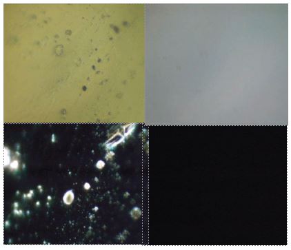
Figure 1 above shows optical micrographs of polished YAG Rod ends before and after cleaning at 1000X.
Left Image: Before and Right Image: After polymer removal. Top: Brightfield and Bottom: Darkfield.
SEM, XPS and AFM are used as needed and results using these techniques are soon to be published in a subsequent paper.
To image the polished YAG rods in Figure 1, an adjustable jig with tilt suspended the polished YAG rod ends in the microscope and the surface was cleaned in place by brushing on liquid polymer and allowing it to dry before removal with one of the peel tabs provided. Some of the contamination in Figure 1 was from fingerprints that appear to be completely removed. As published in multiple placed and here, there is no optically detected residue post polymer removal.3 As a consequence of the complete absence of optically detected residue, it was thought that that Laser Damage Testing (LDT) would be an example of the ultimate test for surface cleanliness. Since LDT should be extremely sensitive to residual surface contamination because the laser damage mechanisms themselves are so nonlinear in their intensity dependence. It is one hypothesis of this research that is possible that the LDT work can be correlated to surface cleanliness in a manner that LDT, combined with using First Contact Polymers can be used in the future for surface cleanliness corroboration and that the more difficult, time consuming and expensive XPS and AFM can be avoided on a routine basis. This remains to be tested and evaluated.
Experimental Details
The LDT system consists of two nanosecond YAG’s, a 600mJ doubled and tripled Continuum Surelite and a 50mJ Minilite II with doubling, tripling and quadrupling optics. The Q-switch and motion stages are controlled from a LabView based data acquisition and control platform that steps the wafer across the beam creating rows of damage spots. Z-translation of the sample into and out of the beam waist serves to change the intensity that is monitored with an absolute spectroradiometer, an RJ-7620 Energy Ratiometer, by Laser Precision Corp, with both a pyroelectric and thermopile.
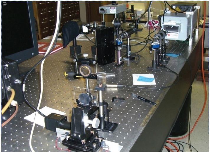
Figure 2 above shows a Continuum doubled, tripled and quadrupled Continuum YAG systems for the basis of our Lab View controlled LDT test station in which the samples are z-translated through the beam waist for intensity control and the Q-switch is controlled as the sample automatically translated on a nanomotion stage to create the array of spot seen in a later figure. In line neutral density is used to control power and the spectroradiometer’s Joulemeter and thermopile can be seen in front of the laser next to the ND filter array. The silicon wafer being tested can be seen in the foreground attached to a glass slide.
Each row is manually examined under a darkfield microscope and the % of shots in that row that resulted in damage is manually tallied and plotted to result in the LDT curve. For simplicity in these initial studies, it was decided that translation of the sample through the beam waist as a means of intensity control was acceptable. While not ideal, as a means of controlling laser spot intensity it seems preferable to moving the beam waist by lens translation or changing the laser power and hence the beam characteristics for a pulsed laser. While it is likely that some beam profile cross section changes do occur as the sample is translated thru the beam waist, thermal lensing changes as the flashlamp power was changed probably would cause more beam profile change upon translation through the focus. Ideally, a vacuum spatial filter or operation of the system in the far field will be used in the future to provide enhanced beam quality at the surfaces to be tested and will be evaluated in the future. Fresnel diffraction rings were observed in the near field before the focusing lens and so the possibility of onset of damage via hotspot render our results accurate only to within a factor of perhaps 5 at this time. The beam waist at the focus was scanned with a pinhole to determine spot size and alternately, burn paper or the laser damaged spot itself used to estimate spot size and therefore determine the intensity. Once again, such estimates can only be considered to be accurate within a factor of perhaps 2-5, limiting our current process’ accuracy.
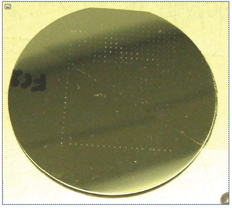
Figure 3: An enlarged image of the wafer post testing with the laser damaged rows. The system sequentially makes rows at different power levels by stepping the sample and opening the Q-Switch. Either a spot or a line focus is used. The rows are then examined under a dark field microscope to determine whether or not each shot caused surface damage. While a digital tabulation of damage vs. no damage works, better statistical trends and curves are found using a process that estimates the relative area of damage spots relative to one another.
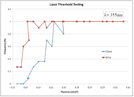
In Figure 4 above, the statistical average of 355 nm laser shots that result in damage on a silicon wafer on our new LDT system. Polymer cleaned and uncleaned wafer surface with a fingerprint smear are shown. Clearly, onset of damage is delayed for the cleaned sample.
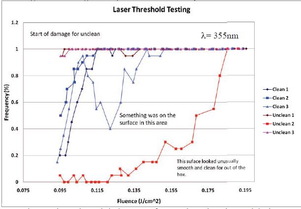
In Figure 5 above, the statistical average of 355 nm laser shots that result in damage on a silicon wafer on our new LDT system. Polymer cleaned and uncleaned sections of wafer were tested. Wafers were taken directly from the box. It became apparent during testing that it was possible to see the effects on de-creased damage threshold due to the low quality of the surface finish of these “cheap’ wafers. A series of runs on Si wafers show the effects of slight contamination and surface roughness on the results.
Summary & Discussion
Corroborating surface laser damage threshold testing at 1064 nm of high power laser optics was performed by a contract lab on new high power laser YAG laser optics with an 1064nm HR coating on BK7. In this work, the LDT was found to be 15J/cm2 at 20ns and 20Hz and with four new substrates, two protected during shipping with First Contact Polymer and two in new normal commercial packaging, the surface LDT was found to be statistically indistinguishable. Surface roughness and poor sample surface quality definitely affects the results and more uniform samples will be used in the future. This work, combined with the work contained herein clearly indicate the benefit of cleaning already “clean” substrates to maximize surface damage threshold.
Future Work
Work is in progress to develop good statistical LDT data for a variety of types of contamination on a variety of substrates ranging from mirrors and optics to gratings to nonlinear optical and other crystals and coatings. Multiwavelength work and image subtraction of before and after damage to more accurately quantitate the extent of damage are being used to improve the process.
It should be noted that the PI, Professor Hamilton has an ownership interest in the company that manufactures and sells First Contact Polymers. We acknowledge and thank Dr. Jonas Baltrusaitis at the Central Microscopy Facility at the University of Iowa working with us to obtain the XPS data in Table 1.
REFERENCES
1 3M made an orange material back in the early 80’s, Universal Photonics makes X-59 and Blue Coat and
Collodion USP has existed for nearly 100 years. The tests in reference 2 below demonstrate that these are for protection, not cleaning and leave significant residue.
2 J. M. Bennett, L. Mattsson, M. P. Keane, and L. Karlsson, “Test of strip coating materials for protecting
optics,” Appl. Opt. 28, 1018-1026 (1989).
3 Bennett, J, Ronow, R, Applied Optics, 39(161), June 2000.
4 J. M. Bennett and L. Mattsson, Introduction to Surface Roughness and Scattering, Second Ed. (Optical
Society of America, Washington, D.C., 1999), pp. 29-33, 62-66
5 Personal Communication, Dr. Philip Chen, Contamination Engineering Group Leader at NASA/GSFC
(Goddard Space Flight Center).
6 “Surface cleaning of CCD imagers using an electrostatic dissipative formulation of First Contact”, G.Derylo, J.Estrada, B.Flaugher, J.Hamilton, D.Kubik, K.Kuk, V.Sparpine,. SPIE Proceedings Vol. 7018 Advanced Optical and Mechanical Technologies in Telescopes and Instrumentation, Eli Atad-Ettedgui; Dietrich Lemke, Editors, 701858, 23 July 2008 DOI: 10.1117/12.789654
7 See www.photoniccleaning.com for details.
8 See http://www.aqmd.gov/rules/index.html for details.
9 NASA GSFC performed ESCA (XPS) analysis on glass and silicon surfaces and confirmed the results of reference 2 for the First Contact Polymer coatings. “Residue from First Contact strippable cleaner ,“ Analysis Number: MATG 3179, October 24, 2006, Report by Dr. John S. Canham, Swales Aerospace, Inc.
10 “Experiments using First Contact polymer as a final cleaning step for aluminizing, “Greg Barrick, Marc Barila, Tom Benedict, Philip Jackson, James Hamilton, (June 2008) , SPIE Proceedings Vol. 7018 Advanced Optical and Mechanical Technologies in Telescopes and Instrumentation, Eli Atad-Ettedgui; Dietrich Lemke, Editors, 701858, 23 July 2008 DOI: 10.1117/12.787642
11 Personal Communication, Tim Saloga, Optics Technician, W.M. Keck Telescope, Waimea, HI.
12 http://outgassing.nasa.gov/ search for First Contact.
13 Report LIGO-T060051-00-D R039, JPL ANALYTICAL CHEMISTRY LABORATORY, Analytical Chemistry and Materials Development Group 3531 Thermal and Propulsion Section 3530. March 2006.