This document outlines the procedures for spraying First Contact (FC) onto vertical aLIGO optics for cleaning and alignment purposes. Directions for removing the dried FC film and handling accidental overspray, drips, or FC residue are also provided. For both cleaning and alignment, specialty cone fixtures are used for precision application of the polymer and protection of the optics and the surrounding area. Spray application is the recommended cleaning method for both sides of suspended optics in the QUAD, BS, and HLTS suspensions; and the HR side of optics in HSTS suspensions.
2 RELATED DOCUMENTS
·LIGO-E1300029: DCN, HSTS/HLTS/BS STRUCTURE, SPRAY GUARD ASSY
·LIGO-D1200490: ALIGO, COC, ETM/ITM FC SPRAY GUARD ASSY
·LIGO-D1300031: ALIGO, SUS, BS STRUCTURE, FC SPRAY GUARD ASSY
·LIGO-D1300020: ALIGO, SUS, HSTS STRUCTURE, FC SPRAY GUARD ASSY
·LIGO-D1300043: ALIGO, SUS, HLTS STRUCTURE, FC SPRAY GUARD ASSY
·LIGO-G1300049: Quad Spray Cone Assembly Video
·LIGO-E1000079: First Contact Brush and Pour Application
·LIGO-E1100439: General Optics Cleaning Procedure
·LIGO-T1200321: Guidelines on Protecting the Cavity Optics in Chamber
·LIGO-T1200198: First Contact Application Layer Scenarios
·LIGO-T1300687: Guidance on Top Gun Ionizing Air Gun System – From Gas to Gun
·LIGO-E1201035: aLIGO Chamber Entry & Exit Guidelines
3 SAFETY (Googles and Respirators / Masks)
Safety glasses or goggles are required when working with all chemicals including First Contact. In addition going forward respirators are required when spraying first contact in chamber and or in an enclosed space. As we go into vacuum there
will be less and less doors coming off so more and more enclosed spaces. Hence why this is coming into effect as a requirement now. Users should be fitted with either 1) 3M 6100/07024 respirator with replacement filter cartridges 3M 60923 (Organic Vapors & Acid gas) OR 2) 3M 6200 respirator with replacement filter cartridges 3M 6001 (Organic Vapors). Note - The 6100 and 6200 respirators can accept the same filters. For low volume effort in well ventilated areas users can use a 3M Particulate Respirator 8247 (R95) or N95 or LIGO stocked PAPR instead. (Final sentence added 12/17 and cross referenced directly from LIGO-E0900479-v2).
4 IMPORTANT FIRST CONTACT INFORMATION
There are two varieties of FC cleaning polymer and FC Thinner – clear & red. The spray application procedure only uses the “red” forms. Red FC Thinner is not actually red; it is the thinner with the right solvent combination to use with the Red FC.
Please
note the following compatibility of FC and common solvents:
·The clear and red polymer solvents and their thinners are NOT compatible. In other words Red FC is used with Red FC Thinner, and Clear FC is used with Clear FC Thinner. Do not mix Red FC/Thinner with Clear FC/Thinner in wet or dry form.
·Isopropanol and methanol are NOT compatible with First Contact. Do not mix them in wet or dry form.
·Acetone IS compatible with First Contact. Acetone can be used to clean up dry FC and FC brushes.
5 CLEANING SUSPENDED OPTICS
5.1REQUIRED MATERIALS
Both
observatories have been provided with spray cones, custom brushes, and spray bottles. Information for ordering additional supplies is given in Table 1.
Table 1. Materials for spray application to clean suspended optics
|
PARTS
|
P/N
|
MANUFACTURER
|
|
Spray cone assemblies
|
QUAD: LIGO-D1200490 BS: LIGO-D1300031 HSTS: LIGO-D1300020 HLTS: LIGO-D1300043
|
SYS
|
|
Wipe templates
|
QUAD: LIGO-D1300277-1 BS: LIGO-D1300277-2 HSTS: LIGO-D1300277-3 HLTS: LIGO-D1300277-4
|
SYS
|
|
Large and small brushes
|
N/A
|
COC (custom made by Gordon Brush)
|
|
Red First Contact (1 liter)
|
FCL
|
Photonic Cleaning Technologies
|
|
Red First Contact Thinner (1 liter)
|
TFCL
|
Photonic Cleaning Technologies
|
|
Spray bottles
Small bottle kit (2 oz) Additional nozzles
|
SBKS SPS
|
Photonic Cleaning Technologies
|
|
Fine PEEK mesh
|
9289T11
|
McMaster Carr
|
|
Wipes
Texwipe Vectra Alpha10 wipes (9” x 9”) Texwipe Alpha wipes (24” x 44”)
|
TX1010 TX1025
|
VWR
|
|
Glass beaker (20 mL)
|
89000-194
|
VWR
|
|
Flashlight array
|
LIGO-D1300223
|
SYS
|
|
Kapton tape
|
7639A75
|
McMaster Carr
|
|
Top Gun System
|
LIGO-D1300948
|
SYS
|
|
Safety glasses
|
N/A
|
General lab supplies
|
|
Scissors
|
N/A
|
General lab supplies
|
|
Respirators / Masks
|
Refer to section 3 above.
|
Refer to section 3 above
|
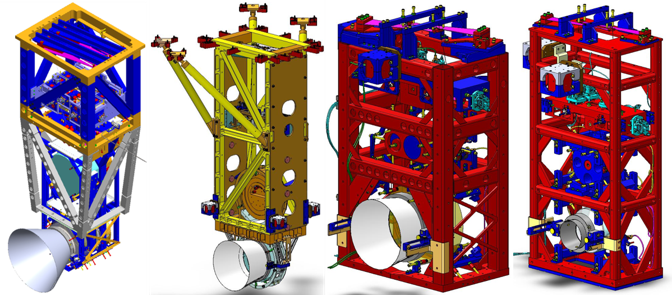
Figure 1. Protective spray cones on QAD, BS, HLTS, and HSTS (from left to right)
5.2 APPLICATION PROCEDURE
The spray guard designs vary slightly for each type of suspension, as illustrated in Figure 1. Despite these differences,
the general procedure for assembling and attaching the cones to the suspensions is roughly the same. First time users should reference LIGO-G1300049, an instructional video on how to assemble and attach the spray cones to the structures.
5.2.1 Assembling Spray Cone Fixture
1) Assemble the Mt. Ring Assy and Spray Guard Assy, as shown in Figure 2. These should arrive on site already assembled, Class B cleaned, and ready to use. If these parts have not been pre-assembled, follow assembly procedures video using appropriate cone drawing (listed in Table 1) for reference.
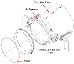
Figure 2. Assembly of HLTS spray cone
2) Attach the Mt. Ring Assy to Spray Guard Assy. The required pines and retaining rings will be provided.
3) Cut a wipe into a T-shape. Use appropriate template from LIGO-D1300277 to cut a 24" x 44" Alpha wipe. This process will release fibers and particulates, especially if dull scissors are used. After cutting, shake out wipe and use a Vectra Alpha10 wipe saturated with IPA to clean the work area and template. If available, use a TigerVac vacuum cleaner to clean the T-shaped wipe and work area.
4)Fold the T-shaped wipe around the CR wipe band. The folding procedure, demonstrated in LIGO-G1300049, is important because the cut edges are wrapped inside the folds to reduce shedding. Fold the wipe as tightly and evenly as possible around the reusable CR wipe band so the wipe does not become lumpy. Secure the wipe to the CR wipe band with Kapton tape.
5)Wrap the wipe + CR wipe band around the Mt. Ring Assy. The wipe should be wrapped tightly, and secured with the o-ring. The two ends of the wipe should connect at the 12 o’clock position, when placed against the optic. The connection of the wipe ends should be as smooth and even as possible so there is no gap for First Contact to leak through.
5.2.2 Preparing Suspension and Surrounding Area
The
suspensions and their surrounding areas must be prepared prior to using the bolt-on cones.
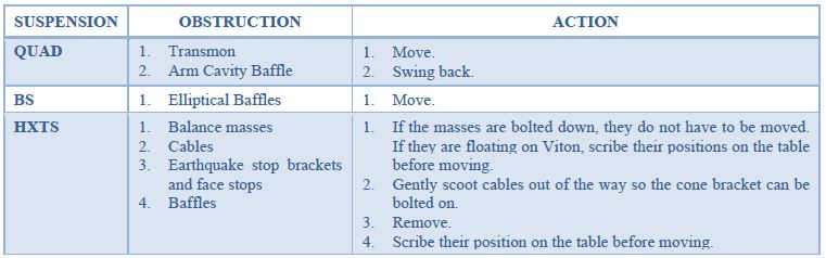
1)Remove obstructions. Only remove objects if they will seriously impact the use of the cones in chamber. Table 2 lists obstructions for each type of suspension, and the Systems-approved method for dealing with them.
Table 2. Potential obstructions for each type of suspension
2) Lock down the structure.
For the QUAD, at least the test mass optic and penultimate mass on both the main chain and reaction chain should be locked. For the HSTS, at least one stage should be locked. Have a SUS expert double-check the structure has been properly locked down BEFORE attaching the cone.3) Remove face stops and earthquake stop brackets. This step is required only for HSTS’s, and only for the side of the optic that will be cleaned.
4) Photograph the optic. This step is optional, but helpful for comparison post-cleaning.
5.2.3 Attaching Spray Cone Fixture to Suspension
1) Lock cone in the “retracted” position. The cone has two positions – retracted (the furthest distance from the optic) and “in-service” (pressed against the optic), as shown in Figure 3 through Figure 6. The retractable spring plunger is used for coarse position adjustment, and the thumb screw is used for fine adjustment.. Pulling up on the plungers allows them to move between two holes in the spray guard slides. Lines are scribed on the top of the slides to make finding the holes easier. Lock the plungers in the retracted position.Adjusting
the thumb screw changes the position of the PTFE guide rail relative to the Aluminum carriage assembly. Back the thumb screw off until the grooved dowel pins cannot be pushed back any further in the threaded block, as shown in Figure 3.
Note: Continuing to adjust the thumb screw after the dowel pins are pushed all the way back will disengage the screw from the carriage assembly.
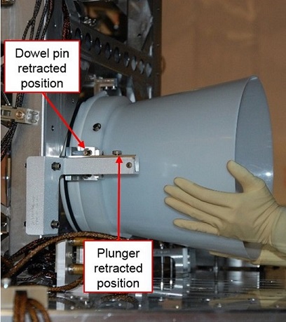
Figure 3. Attaching the HLTS cone in the retracted position to PR3 (side view)
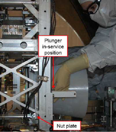
Figure 4. Adjusting thumb screws to move the cone to the in-service position on PR3 (side view)
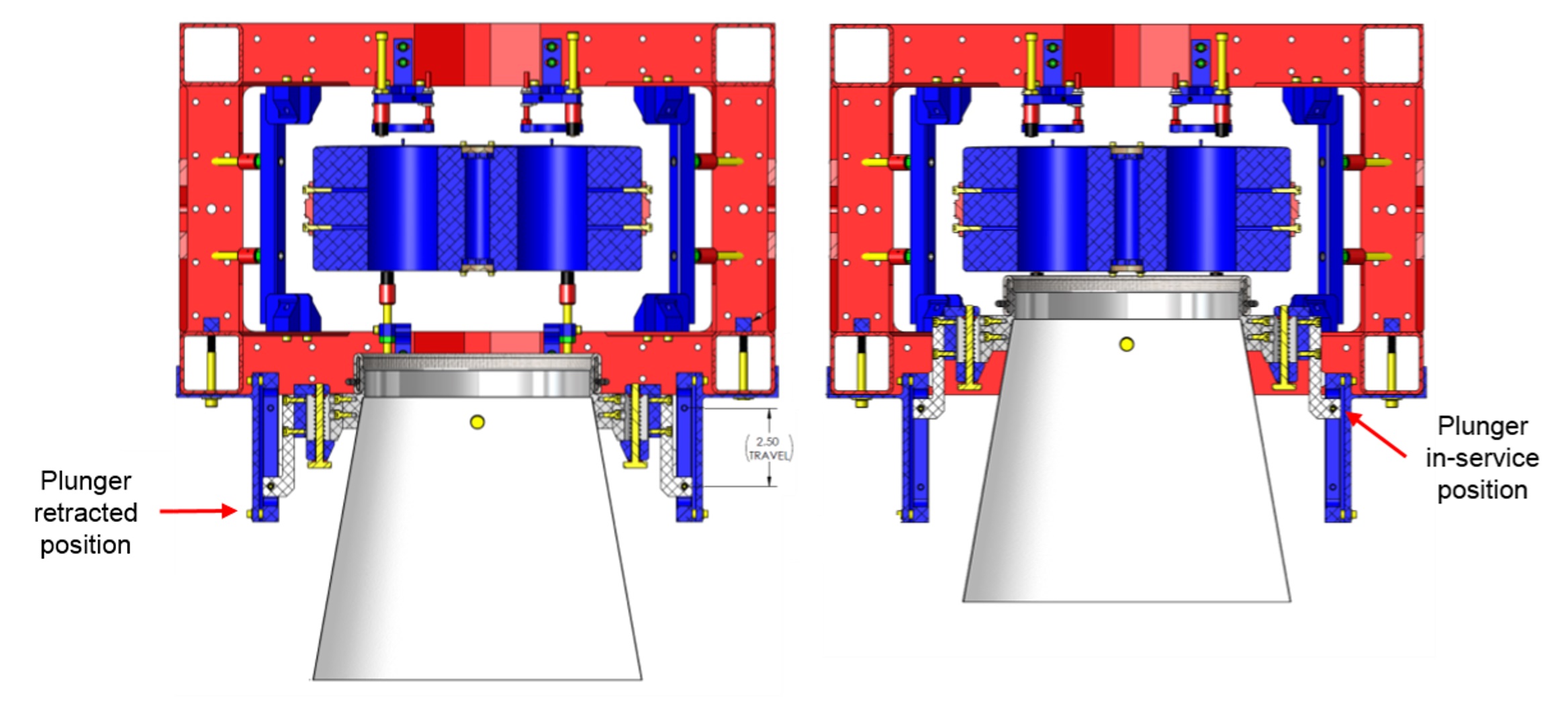
Figure 5. HLTS cone in the retracted position (top view) aaaaaaaaaaaaa Figure 6. HLTS cone in the in-service position (top view)
2) Attach the cone assembly to the suspension. Each drawing calls out the appropriate screw sizes for attaching the cone fixtures. The HLTS cone uses two nut plates (LIGO-D1300041) in addition to screws.
3) Move the cone into the in-service position. Pull up on the retractable spring plungers, and slide the cone towards the optic until the plungers click into place. Turn both thumbscrews at the same time to firmly and evenly seal the cone against the optic. Check the seal with the flashlight array.
4) Double-check wipe ends meet at the 12 o’clock position. As shown in Figure 7, FC spray can escape at the point where the ends of the wipe meet. Overspray is prevented by a good seal, and placing the end of the wipes in an area that encounters less spray. More FC will accumulate at the 6 o’clock position as the spray runs down the optic.
5) Place wipes around the optic. Vectra Alpha 10 wipes below the optic and cone are an additional protection measure against drips.
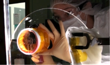
Figure 7. Overspray at 12o'clock position on prototype cone
5.2.4 Preparing First Contact Spray
The
steps in this section are performed outside the vacuum chamber.
1) Don protective eyewear. Always wear safety glasses/goggles when spraying First Contact.
2) Clean beaker and spray bottles. Rinse out the beaker with acetone. Rinse or spray the bottles with Red First Contact Thinner or acetone before using for the first time.
3) Mix First Contact spray. Use the beaker to measure out 1 part Red First Contact to 1 part Red First Contact Thinner. Pour the mixture into one of the two clean spray bottles. Cap the bottle.
4) Flush nozzle. Pour Red FC Thinner into the other clean bottle and screw the nozzle on. Flush the nozzle by spraying the FC Thinner into a wipe until the spray comes out completely clear. Remove the cap from the bottle with the FC spray mixture, and replace with the nozzle from the thinner bottle. Cap the thinner bottle. These steps are highlighted in Figure 8.
Note: Acetone can be used in a pinch to flush the nozzle. No other chemicals can be used.
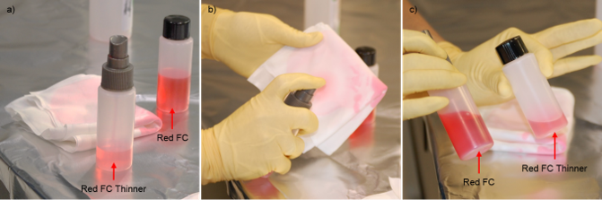
Figure 8. a) Capped bottle of Red FC spray mixture and bottle of Red FC Thinner with nozzle, b) Flushing nozzle with thinner, c) Capped bottle of Red FC Thinner and bottle of Red FC Thinner with nozzle
5) Test spray. Pump the nozzle into a wipe until the spray comes out pink. Now the nozzle is primed and ready to go. The FC should come out in a mist, not a glob. The nozzle will gum up if it has not been flushed with thinner in a while. If the nozzle does not work after flushing, get a new nozzle.
Note: First time users should practice spraying FC onto a vertical surface, such as foil or plate glass.
5.2.5 Spraying First Contact
The steps in this section occur inside the chamber unless otherwise noted. While the procedure can be completed by a
single person, it is preferable to have two people in the following roles:
· Person 1 (aka the nurse) – Hands off necessary materials to Person 1, angles the flashlight array, monitors distance between the FC spray bottle and optic, flushes the nozzle and cleans the brush if necessary.
·Person 2 (aka the surgeon) – Applies First Contact.
·Both – Check the seal between the optic and cone, and also watch for drips, overspray, and “spider webs.”
Note: If there is too much polymer in the solution, then it will dry almost the instant it is released through the nozzle, creating spider webs, as seen in Figure 9.
1) Collect materials in pan. Outside the chamber, Person 1 gathers the FC spray mixture bottle with primed nozzle and Vectra Alpha10 wipes in a clean pan. A tall pan is preferable so the bottle cannot be knocked out accidentally.
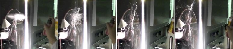
Figure 9. Creating of spider webs on glass plate
2) Move into position. Person 2 moves into position in chamber in front of the spray cone. Person 1 passes the pan of materials to Person 2, then moves into a position that allows for close viewing of the optic. Person 1 angles the flashlight and acts as a second set of eyes.
3) Spray layer of First Contact. Person 2 sprays a full coverage layer of FC inside the cone using the optic face-to-nozzle distances in Table 3. There is a natural tendency to move the bottle further away from the optic when spraying, especially when trying to angle the bottle to spray the upper edges of the cone. This can result in accidental overspray and spider webs. The optic face-to-nozzle distances were defined to mitigate these problems. Person 1 should closely monitor the nozzle distance and angle.
Note: The FC will seep into the wipe, as seen in Figure 11. Watch for FC leaking out of the wipe, especially at the 12 o’clock and 6 o’clock positions. If any overspray or leaking is observed, STOP spraying immediately and adjust the cone against the optic to get a tighter seal.
Table 3. Recommended optic face-to-nozzle distance
|
OPTIC FACE
|
DISTANCE FROM OPTIC
|
|
HSTS HR
|
2.5”
|
|
HLTS AR
|
3.5"
|
|
HLTS HR
|
Not as important as small sizes. Nozzle must remain inside the cone.
|
|
QUAD AR & HR
|
Not as important as small sizes. Nozzle must remain inside the cone.
|
|
BS AR & HR
|
Not as important as small sizes. Nozzle must remain inside the cone.
|
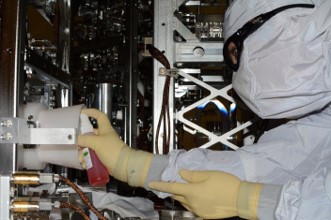
Figure 10. Person 2 spraying FC onto PRM with nozzle at the max acceptable distance from the optic face
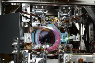
Figure 11. View from AR side of MC1 during spray application of FC on HR side
4) Wait 2-5 minutes for FC to dry. Leave the cone in place against the optic. The nozzles do not need to be flushed yet unless it becomes clogged.
5) Spray two more layers of FC. Spray a second full coverage layer of FC inside the cone using the same optic face-to-nozzle distances. Wait 2-5 minutes for the FC to dry. Then repeat for a third layer, and allow to dry.
6) Wait 2-5 minutes for third layer of FC to dry.
7) Move the cone into the retracted position. Use the thumb screws to back the PTFE guide rail off as much as possible. Then slide the spring plungers into the start position to completely disengage the cone from the optical surface.
Note: Check for overspray or thin spots of FC. If the FC looks too thin, move the cone to the in-service position again and spray an additional layer of FC.
8) Detach the cone assembly from the suspension.
9) Remove cone assembly and pan from chamber. Person 1 removes the entire cone assembly (including screws) and the pan of materials from the chamber, while Person 2 continues to inspect the optic.
10) Collect brush materials in pan. Outside of the chamber, Person 1 cuts a ~0.5” x 2” strip of PEEK mesh, and pours ~10 mL of Red FC into a clean beaker. The FC spray bottle is removed from the pan, and is replaced by the strip of PEEK mesh, beaker of FC, and a clean brush.
Note: The Red FC should not be poured in advance because it will thicken and be harder to apply.
11) Pass pan of materials into chamber. Person 1 hands the pan of materials to Person 2. If needed, Person 2 can lay out additional wipes to catch drips.
12) Paint a “pie crust”. The outer edge of the sprayed FC must be thickened so the entire film can be pulled off in one piece when it dries. Get as much FC on a custom brush as possible without dripping, and carefully paint a ring, aka pie crust. The brush should be centered over the edge of the sprayed FC circle, so half of the crust is inside the FC circle and half is outside. Include all sprayed and thinly covered areas in the crust, even if this means the end result is not a circular crust. Carefully inspect the crust with the flashlight array to ensure there are no gaps.
Note: The FC does not need to look pretty. Focus on getting a thick crust, and including any oversprays or drips. The brush will become sticky and possibly create spider webs, especially if it is used over areas that were just painted. If this happens, stop and clean the brush (see Step 14) before continuing.
13) Wait 5-10 minutes for the crust to dry.
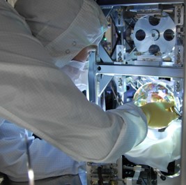
Figure 12. Painting pie crust on MC1
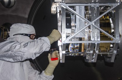
Figure 13. Painting pie crust on ITMX
14) Clean the brush. While waiting for the FC crust to dry, Person 1 should remove the brush from chamber for cleaning. Replace the nozzle from the FC spray mixture bottle with a cap. Put the nozzle on the Red FC Thinner bottle. Flush the nozzle with thinner. Lay the brush on wipes, and spray with thinner. Use a wipe to remove the excess FC. Continue spraying and wiping the brush until it is clean. Person 1 hands the clean brush to Person 2.
15) Paint two more pie crusts. Gently touch the first pie crust with the clean brush. If the FC feels tacky, allow it more time to dry. Paint a second pie crust directly over the first, allow 5- 10 minutes for it to dry, and clean the brush. Then paint a third crust directly over the first two. Do not allow it to dry before moving onto the next step.
16) Add a PEEK tab. While the third pie crust is still wet, hold the PEEK mesh strip against the crust on either side of the optic (in the 2-4 o’clock or 8-10 o’clock regions). About half of the PEEK should be on the crust, and half should extend past it. Hold the PEEK tab with one hand, and use the other hand to dab FC onto the portion of the strip that is on the crust with the brush.
Note: The PEEK tab be applied to an already dry film. The FC will dissolve in the solvent and recombine into a new layer. However, it is saves time to add the strip after applying FC.
17) Let the PEEK tab dry for at least 1 hour.
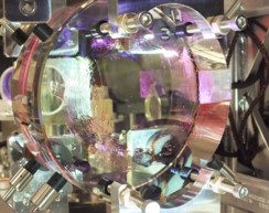
Figure 14. Dry FC with PEEK tab on MC1
5.3 REMOVAL PROCEDURE
Ideally, the area around the optic should be cleaned first, and the FC dry film should be removed just before the closing the chamber to minimize the amount of contamination the optic is exposed to.
1) Set up the Top Gun Ionizing System. Refer to LIGO-T1300687 for the procedure.
Note: Do not exceed 10 psi!
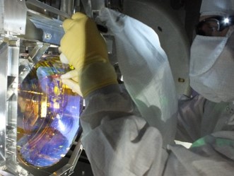
Figure 15. Pulling PEEK tab while using Top Gun
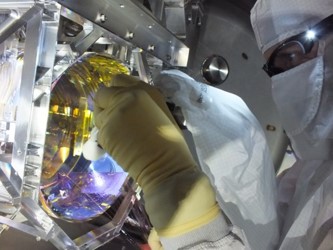
Figure 16. Peeling dry FC while using Top Gun
2) Peel First Contact while using the Top Gun. Holding the ion gun in one hand, slowly start to peel the PEEK mesh tab off the surface of the optic.
Note: If the FC does not start to come off in a single piece as the tab is pulled, STOP and re-apply a thick FC crust.
3) Peeling First Contact. As soon as the dry FC film begins to detach from the optical surface, start blowing nitrogen from the ion gun onto the optic. Hold the gun parallel to the optic face, focusing on the area where the film is detaching from the optic. The Top Gun should be ~ 4” from the optic surface. Pay close attention to the edges when peeling to ensure nothing is left behind on the optic.
Note: for the case of the ETM / ITM chains apply the following (& adjust as required for other optics. If input needed for other optics talk to COC / SYS groups at CIT.) : -
(i) Blow between the gap of the two optics first for a small period of time (with FC still on ERM and HR of main optic) to dislodge any large debris.
(ii) Clean barrel of both optics (as per LIGO-E1100439-v6) with acetone & Berkshire lens tissue) and then blow barrel with top gun for up to 1 minute. (If acetone gets onto FC on face ensure it is dry before removing FC.).
(iii) Then starting with the ERM first contact, take around 1 minute to slowly peel this FC (blowing with top gun at the same time).
(iv) Then on top of that blow for an additional 30 seconds on the freshly peeled ERM surface.
(v) Now take ~2min to peel FC from HR of main optic, blowing with top gun the whole time.
(vi) Then again on top of that blow for an additional 30 seconds on the freshly peeled ERM surface.
4) Continuing with Top Gun after peel. As noted above it is essential to continue with Top Gun after FC is pulled. Tests have shown that in order to remove all residual charge, it is essential to continue with the ionization of the surface (with the top gun) for 30 seconds per large optics (ETM sized) surface. For smaller optics blowing should continue for 30 seconds (HLTS) and 20 seconds (HSTS) after FC is pulled.
5) Discharge Procedure. Now perform the discharge procedure, refer to LIGO-T1500101-v3: ETM / ERM Gap discharge procedure & ITM / Cavity Optic discharge procedure for full details on the discharge procedure. [It should be noted that ahead of this clean-up step local conditions should be considered e.g. is there dust on the barrel.]
6) Measure charge. Measurements of the residual charge should be made with an electrometer from Alpha Lab Inc #VSVM2, refer to LIGO-E1500457: Instructions, Archive of AlphaLab App .exe files & Trifield links for USSVM2 Electrometer. For the ETM / ITM the electrometer should be mounted adjacent to the face of the ERM / CP via LIGO-D1500139: ETM/ITM, Electrometer mounting fixture. [It should be noted that at the time of writing the suite of holders to allow use of electrometers on all optics is pending. If no mount available one should still discharge as per #5 utilizing the electrometer safely.]
7) Inspect the optic for residual FC. Shine the flashlight array around the outer optic face to check for any stray FC. If the procedure is followed correctly, all FC should have been removed from the optic. If all of the FC was successfully removed, this is the end of the procedure. If there is residual FC left on the optic, refer to Section 6.
8) Green Lantern At this point one could also use the Green LED flashlight (of the order 300 lumen) or the Green Lantern, LIGO-D1400060 to inspect the optical surface.
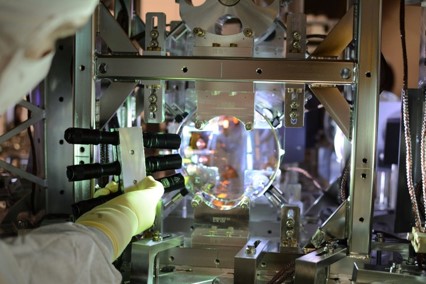
Figure 17. Inspecting MC1 with flashlight array
6 ALIGNMENT LAYER
No longer used. If an optic with an alignment layer is found then one should contact COC
/ SYS team. If this does occur then it is important to note that not only must the alignment layer must be thickened (via spraying 2 thick layers of first contact) before removal but also one must follow the alignment layer application steps in v4 of this document. Once the FC has dried, remove the whole sheet following the procedure in Section 5.3 of this revision.
7 RESIDUAL FIRST CONTACT
How to deal with residual First Contact depends on the optic and location of the FC. For each optic,
LIGO-T1200321 defines which of the three removal methods should be used based on the location of leftover FC.
7.1 RE-CONING
Repeat the entire spray application and removal procedure per Section 5. The required materials for the procedure are
also listed in Section 5.
7.2 SPOT BRUSHING
7.2.1 Required Materials
Table 4. Materials for spot brushing
|
PARTS
|
P/N
|
MANUFACTURER
|
|
Small brushes
|
N/A
|
COC (custom made by Gordon Brush)
|
|
Red First Contact (1 liter)
|
FCL
|
Photonic Cleaning Technologies
|
|
Red First Contact Thinner (1 liter)
|
TFCL
|
Photonic Cleaning Technologies
|
|
Small First Contact applicator
|
RFCAB
|
Photonic Cleaning Technologies
|
|
Fine PEEK mesh
|
9289T11
|
McMaster Carr
|
|
Texwipe Vectra Alpha10 wipes (9” x 9”)
|
TX1010
|
VWR
|
|
Glass beaker (20 mL)
|
89000-194
|
VWR
|
|
Flashlight array
|
LIGO-D1300223
|
SYS
|
|
Safety glasses
|
N/A
|
General lab supplies
|
|
Scissors
|
N/A
|
General lab supplies
|
7.2.2 Procedure
1) Don protective eyewear.
2) Paint on a layer of FC. Use either the small custom brush or small applicator to paint a thick layer of FC directly over the residual FC. The new layer should be roughly the same shape of whatever was left behind, and just slightly larger so the edges are thick enough to remove easily.
3) Wait 5-10 minutes for FC to dry.
4) Clean the brush. Use Red FC thinner and wipes to clean the brush.
5) Paint two more layers. Paint a second layer of FC, allow 5-10 minutes for it to dry, then paint a third layer.
6) Add a PEEK tab. While the third layer is still wet, place a PEEK mesh strip over the FC. About half of the strip should extend past the FC. Dab FC onto the tab.
7) Let the PEEK tab dry for at least 1 hour.
8) Remove the FC per Section 5.3.
7.3 ACETONE WIPING
7.3.1 Required Materials
Table 5. Materials for acetone wiping
|
PARTS
|
P/N
|
MANUFACTURER
|
|
Berkshire Lens X90 tissue
|
LN90090916P
|
VWR
|
|
Absorbond swabs
|
TX762
|
Quintana Supply
|
|
Flashlight array
|
LIGO-D1300223
|
SYS
|
|
Safety glasses
|
N/A
|
General lab supplies
|
|
Acetone
|
N/A
|
General lab supplies
|
7.3.2 Procedure
1) Don protective eyewear.
2) Drag-wipe residue with acetone. Use only a Berkshire Lens X90 tissue soaked in acetone to wipe in a circular fashion, moving the tissue/swab outward toward the edge of the optic. The middle of the optic should be the cleanest area, so wiping inward will drag any contaminants towards the center, and is therefore not recommended. Use the flashlight array to ensure all of the FC is removed.
Note: A note of caution on the Berkshire/acetone approach. This method often leaves light residue - this residue is not a problem around the edge of an optic (~1 cm or so, depending on beam size) also not a problem on barrels etc. The acetone is ideal for removing first contact. Acetone will attack the alpha wipes (and gloves etc...) leaving a sticky residue - thus the need to use the Berkshire wipes with acetone. Avoid this contamination by only gripping dry sections of the tissue/swab, or hold the tissue with round tipped forceps. Berkshire/acetone is NOT recommended for any place in the beam path.
Additional Note: Alphaswabs with e.g. IPA is still okay to use on the barrels of e.g. ETM’s / ITM’s to aid with removing other contaminations but not for FC.
7.4 Residual Charge
It is essential that after any “cleaning” on the optic face or barrel i.e. the methods described in this section that one uses the Top Gun System at 10 psi for a few seconds on the freshly cleaned area to remove any charge deposited by the “cleaning” steps.
|
|
|