Click the green title text if you would like to download the document
First Contact Polymer as Final Step Prior To Aluminizing
Advanced Optical and Mechanical Technologies in Telescopes
and Instrumentation, Eli Atad-Ettedgui; Dietrich Lemke, Editors, 70185B. DOI:
10.1117/12.787642
Gregory Barrick*a, Marc Barila, Tom Benedicta, Philip
Jackson
b, James Hamiltonbc,
aCanada-France-Hawaii Telescope, 65-1238 Mamalahoa Hwy, Kamuela, HI, USA 96743
bPhotonic Cleaning Technologies, P. O. Box 435, Platteville,
WI, USA 53818
cChemistry & Engineering Physics, University of
Wisconsin-Platteville, Platteville, WI, USA 53818
* [email protected]; phone 1 808 885-7944; fax 1 808
885-7288;
www.cfht.hawaii.edu
ABSTRACT
Cleaning mirrors for coating is a very exacting process and
for larger mirrors it can be physically demanding. The final step of cleaning and drying the
substrate is particularly problematic.
Non-contact drying methods, usually with compressed air or nitrogen, can
be laborious and can introduce contaminants if the compressed gas used is
insufficiently pure(just a thought, recontamination is also a problem). These methods also tend to increase the
static charge on the substrate surface, attracting lint. Contact methods tend to add lint or fibers to
the cleaned surface. As an alternative,
we are experimenting with using the First Contact polymer cleaning solution as
the final step in mirror coating preparation. The advantage of this method is
that the polymer coating, which will adhere to much of the remaining surface
contaminants, may be left on the substrate until just before it is placed into
the coating chamber, minimizing the time available for re-contamination. The results of our experiments on small
substrates are presented.
Keywords: coating, aluminizing, mirror cleaning
1. INTRODUCTION
One large challenge in obtaining a good thin film coating is
getting the substrate sufficiently clean to allow adhesion of the film with a
minimum of pinhole defects. The larger
the substrate, the more challenging getting the whole surface sufficiently
clean becomes. Since the cleaning
procedure often takes place at a location physically separated from the vacuum
chamber in which the substrate will be coated, the substrate also needs to be
kept clean up until it is in the coating chamber. Typically this means handling by heavy
lifting equipment for large optics such as telescope primary mirrors.
While most steps involved in the cleaning introduce risks of
contaminating the surface that is being cleaned, the final step, drying,
provides the highest risk for re-contaminating the recently cleaned surface
especially with regards to depositing dust on the surface which will cause
pinholes in the coating if not removed.
Hydrocarbon contaminants can also be deposited on the substrate if the
gas is not sufficiently pure. During the
history of coating the Canada-France-Hawaii Telescope (CFHT) primary mirror,
several different approaches have been used for reducing the amount of residual
dust on the substrate before coating.
These have all worked to some extent, but all have some drawbacks.
One of the original methods used was to dry the surface
using Kimwipe paper towels then brushing the visible lint off using an
anti-static brush. This method was
extremely time-consuming and only removed the dust that was visible and that
was noticed on a 3.6 m diameter surface.
A second method was to dry the surface using Kimwipes then
remove the dust with a CO2 snow cleaning.
This method quickly removes most of the large dust particles. The main problem is that drying with the
towels tends to produce static which often causes the dust, especially the
smaller dust, to adhere to the substrate with a greater force than can be
exerted by the CO2 snow. CO2 snow has also
introduced hydrocarbon contamination when the liquid is not sufficiently pure.
Our recent method has been to air dry the substrate using
compressed, ultra-pure nitrogen passed through an anti-static device to reduce
static charge buildup on the surface. A
CO2 snow cleaning is performed as the substrate is placed into the vacuum
chamber. This method works well over
most of the surface, but has some drawbacks.
The most serious one is that the nitrogen drying is the most physically
demanding step of an already demanding cleaning procedure.
Another drawback is that the surface that has not already
been dried needs to be kept wet without wetting the dried part of the
mirror. This requires the use of
Kimwipes to keep the water within the wet area around the central hole in the
mirror. These Kimwipes leave dusty
patches that then need to be cleaned off, typically with alcohol.
These drawbacks could be eliminated or alleviated with the
use of an air-knife. One main objection
to the use of an air-knife is that using compressed nitrogen in a confined
space poses a health hazard to the operators.
Use of compressed air would be possible if sufficiently pure. Another objection to this is the time
required to design, implement, and test such a device, especially in use on the
primary mirror. This time is in short
supply at CFHT. Finally, this does not
solve the issue of the time between drying and having the mirror in the vacuum
chamber for the mirror to gather more dust.
For this reason, the use of First Contact as a final step in
the substrate cleaning process was put forth.
First Contact consists of an ethanol/acetone-based polymer solution that
can be sprayed or painted on an optical surface; it is manufactured by Photonic
Cleaning Technologies, LLC.
1. Upon
exposure to the air, the solution dries to form an elastic film which traps any
solid particles or soluble contaminants on the surface which are then removed
by peeling the film. The benefits to using First Contact are that it can be
easily tested on smaller substrates but the results can be applied to the
primary mirror, it protects the mirror from further dust contamination until
just before placing the mirror in the chamber, and it is easy to apply. The drawbacks of using First Contact are the
expense and the static charge generated when the polymer sheet is removed from
the substrate, though Photonic Cleaning is working on the latter problem. The former issue, expense, may be offset by
reducing mirror cleaning time, improving chances for a successful coating, and
possibly improved mirror lifetime due to fewer pinhole defects.
At CFHT, a series of experiments on small mirrors has been
run to test if using First Contact as a cleaning step in coating mirrors
produces results at least as good as our standard method (described
below). This paper will describe each
experiment, then give the results of the experiments, and finally give some
conclusions and desired future tests.
2. EXPERIMENTAL SETUP
2.1 Experiment 1
The first experiment was an attempt to see at which point in
the normal coating process First Contact could be introduced and still produce
good results. To prepare for this
experiment, thirty 50 mm square glass plates (microscope slide quality) were
coated using the normal CFHT coating procedure.
Twenty of the samples were subjected to four different storage
conditions for a period of about 6 weeks.
The other ten were stored in a closed container as references.
Before the samples were contaminated and stored, they were
allowed to age for a week in a closed container to allow the aluminum oxide
layer to form. At the end of this week,
photographs were taken of each sample while back illuminated with a uniform
source to show pinholes in the coatings.
Reflectivity measurements were also taken using a TMA reflectometer
which is capable of measuring reflectance and BRDF scattering at a wavelength
of 670 nm. After the measurements were
done, five samples (1 – 5) were contaminated with house water, five more (6 –
10) were contaminated with glycol, and a final five (11 – 15) were contaminated
with hydraulic fluid (all common contaminants for our mirror). All fifteen were dusted with crushed cinder
from outside the CFHT dome while still wet.
These samples were then left exposed in the CFHT dome for 6 weeks. Five more (15 – 20) were stored in a closed
container with no contaminants applied.
The final 10 were unused in this experiment.
At the end of the 6 weeks, the samples were stripped,
cleaned and re-coated. The stripping and
cleaning procedure was as follows: rinse
with house water; rinse with a sodium lauryl sulfate based soap (Orvus) mixed
with de-ionized (DI) water; rinse with house water; drag wipe surface with
cotton soaked in an Orvus/DI water solution; rinse with house water; then with
DI water; apply Green River
2 to the mirror by putting Kimwipes on the surface
and pouring the Green River onto the Kimwipe;
leave this in place until most of the aluminum is gone; rinse with house
water; scrub the surface with cotton soaked in Green River. This process was followed for all twenty
samples. At this point, the processing
diverged for the samples.
1 Photonic Cleaning Technologies, P.O. Box 435, Platteville,
WI, USA, 53818
2 “Green River” is a solution of HCl and CuSO4 (copper
sulfate) in the following proportions:
272 g of 37% HCl to 22.7 g of CuSO4 diluted in 1 liter of de-ionized
water.
Four of the samples, one from each contaminant group, had
First Contact, applied at this point.
The rest of the samples were now rinsed with house water and DI
water. At this stage, four more samples
were coated with First Contact. The
remaining twelve samples underwent two scrubs using cotton and a slurry of DI
water and calcium carbonate (CaCo3) powder with a rinse of house water between
the scrubs. Four more samples were
coated with First Contact after the second scrub but before rinsing. The final eight samples were rinsed and dried
carefully using Kimwipes. Four of the
final eight were then coated with First Contact and the last four were coated,
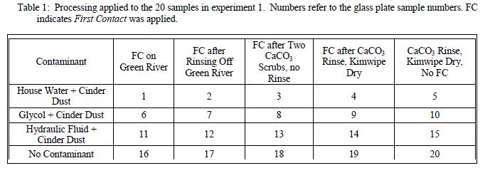
as is. Table 1 summarizes this process
and indicates which samples were used at each step.
At this point, it is worthwhile noting that, in an attempt
to make the First Contact easier to remove, a Kimwipe was placed on each sample
while the First Contact was wet. This
actually made it more difficult to remove the First Contact and left behind a lot
of “fluff”. This was removed using a
second coating of First Contact before coating.
It is important to note that this mistake was due to CFHT inexperience
with using First Contact and not due to any suggestions made by Photonic
Cleaning Technologies. The consequences
of this mistake and what was learned from it are discussed in the results
section of this paper.
he samples were now coated using a 30 second plasma
cleaning stage instead of the normal 10 minute cleaning. The procedure shown, taken all the way
through to the drying stage, is the same as is used on the CFHT primary
mirror. The main difference is that
drying is normally done with compressed air instead of Kimwipes. Plasma cleaning is also available in the
larger vacuum chamber used to coat the primary mirror. A coating of about 600 Angstroms thickness
was achieved on the samples.
After allowing the aluminum oxide layer to form, for six
weeks in this case, the samples were back illuminated and photographed, tape
tests were performed over the entire surface, and the reflectance and roughness
of the samples were measured using the TMA reflectometer.
2.2 Experiment 2
This experiment was done to validate the results of the
previous experiment and to ensure that the plasma cleaning, as short as it was
during experiment 1, did not hide some issue with the cleaning. Plasma cleaning will often allow a less than
perfect cleaning to result in an acceptable coating.
For this experiment, twenty-four of the previous samples
were stripped, cleaned, and re-coated using the standard CFHT coating
procedure. They were allowed to age for
ten days and were then split into four groups: six samples (1 – 6) had no
contamination placed on them, six (7 – 12) had pump oil placed on them, six (13
– 18) had machine oil placed on them, and six (19 – 24) had vacuum grease
placed on them. Shortly after contamination, the samples were processed.
All twenty-four samples were washed and rinsed using Orvus
soap and were then stripped of aluminum using Green River. The samples were cleaned using one of the
following three procedures:
• One CaCO3
scrub followed by rinsing with house water then DI water. Dried with dry nitrogen.
• Two CaCO3
scrubs followed by rinsing with house water then DI water. Dried with dry nitrogen.
• Two CaCO3
scrubs followed by rinsing with house water then DI water. Dried with Kimwipes.
In this case, the Kimwipe drying was done until the surface
was completely dry, as was formerly done with the primary mirror, instead of
only mostly dry, as was done in Experiment 1.
Finally, one of each pair of samples with the same contaminant and the
same cleaning procedure was coated with First Contact to allow a one-to-one
comparison of the methods. Table 2 shows how all the samples were processed.
The mirrors were then coated in two batches, 1- 16 first,
then 17 – 24. A thickness of about 600
Angstroms was achieved. No plasma
cleaning was done.
After several weeks, the samples were measured for
reflectivity and BRDF scatter at a single wavelength, measured for reflectivity
versus wavelength in the CFHT spectrophotometer, back illuminated photographs
were taken, and full sample tape tests were performed.
2.3 Experiment 3
The goal of this experiment was to determine what kind of
contaminants, on a cleaned surface, we can expect First Contact to remove and
still provide a successful coating. For
this experiment, sixteen samples were stripped, cleaned with two CaCO3 scrubs,
rinsed with house water, then DI water, and dried with dry nitrogen. The samples were then immediately
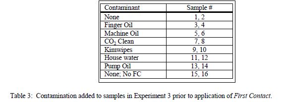
contaminated with a visible level of the substances shown in Table 3. All the samples were then coated with First
Contact except the last two which were used for controls.
All sixteen samples were coated in a single set with no
plasma cleaning done prior to evaporation.
After several weeks, the samples were measured for reflectance and
scatter at a single wavelength, measured for reflectivity versus wavelength in
the CFHT spectrophotometer, back illuminated photographs were taken, and a tape
test was done across the full sample.
3. EXPERIMENTAL RESULTS
3.1 Notes on Tests and Measurements
The photograph setup for the back illuminated images of the
samples was, unfortunately, not consistent over the three sets of samples
photographed (initial aluminization before any tests, results from Experiment
1, and results from Experiments 2 and 3 which were performed at the same
time). The masking of the back
illumination, camera orientation, and even the camera changed from setup to
setup. In addition, the last set was transported
to our headquarters before the photographs were taken and some sustained
scratches in transit. For these reasons,
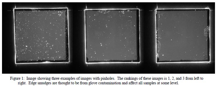
a pinhole area counter was not possible as originally intended. Instead, the images were ranked by eye as to
number of pinholes with a rank of 1 indicating numerous pinholes, 2 indicating
a moderate number of pinholes, and a rank of 3 indicating few pinholes. Some very subjective non-integer ranking was
also applied. Figure 1 shows examples of
images with rankings of 1, 2, and 3.
While this system is somewhat subjective, it is very capable
of differentiating between samples with many pinholes and those with few
pinholes. To keep the ranking somewhat
consistent, three images were used as references for a 1, 2, or 3 ranking and
these images were referred to frequently during ranking of the other images.
n addition, the reflectance measurements from the TMA
reflectometer were done at different temperatures and different pressures for
the different experiments. The
reflectometer is sensitive to these things, so these reflectance measurements
are only good for relative comparisons within a group and are not valid in an
absolute sense. The roughness
measurements should be more valid in an absolute sense.
In Experiment 1, the roughness measurements were done after
the tape tests were performed, so the results of the roughness measurements are
somewhat suspect. However, the
conclusions drawn in this paper do not rely on these data. For Experiments 2
and 3, the tape tests were performed after the roughness measurements were
taken.
Finally, it should be noted that the removal of the First
Contact film from the edges of these substrates proved to be a bit
challenging. The substrates were cut
from 4 mm thick commercial grade plate glass and had sharp corners and edges
that were minimally ground. The sharp
edges tended to separate the First Contact on the surface from the First
Contact on the edge so that it did not all come off together. The front surface layer came off easily, but
the thin edges made detaching3 the residual First Contact more difficult, so
the substrates that used First Contact typically needed to be handled
more. It is felt that on a large
substrate with beveled corners and fine ground edges, this would be less of an
issue.
3 The First Contact film was detached by applying Photonic Cleaning Technologies’ adhesive strips to the film and pulling.
3.2 Experiment 1 Results
The errors that happened while performing this experiment
mean that these results will not be examined in too much depth. However, the results were sufficient to draw
some basic conclusions, at least qualitatively.
The main issue with the results from this experiment was
that the pinhole counts were worse for the samples where First Contact was
used. This, in itself, is not enough to
invalidate the results, of course.
However, the results of Experiment 2, which was done more carefully,
contradict this result. The hypothesis
for the increase in pinholes is that the second coat of First Contact removed
the bulk of the “fluff”, but did not have the capacity to completely remove the
“fluff” thus increasing the pinhole count.
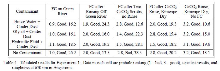
The results of this experiment are tabulated in Table
4. This table has the same entries as
Table 1 except the results are given in place of the sample number. Three results are given in each cell: the pinhole number ranking, the result of the
tape test (normally either good or bad), and the average
roughness measurement over 5 locations.
The reflectance is not reported since all samples were the same to
within a few tenths of a percent.
Although the experiment was not fully controlled, some
conclusions can be drawn from it. First,
the tape test only failed on one sample.
This sample was processed with CaCO3 scrubs, but no rinsing and it was
noted that visible CaCO3 remained after the First Contact was removed from
these samples. It is known that First
Contact will only lift a certain quantity of contaminant before saturating, so
this failure is not unexpected.
The samples on which First Contact was applied after
rinsing, while having more pinholes than hoped for, average pinhole ranking of
1.8 ± 0.6 excluding the failed coating, are in line with the pinhole rankings
of all of the substrates when initially coated (rankings not given here). The average ranking over all the samples
after the initial coating, cleaned in the standard way with no First Contact,
and prior to contamination, was 1.5 ± 0.6 with some much better and some much
worse. During the processing above,
extra care was given to the four samples with no First Contact applied. So,
even with a flawed application of First Contact, the coatings were still
useable in most cases.
A final conclusion one can draw is that First Contact should
not be used without a thorough rinsing of the substrate, though thorough drying
is not necessarily mandatory.
3.3 Experiment 2 Results
This experiment gave very clear results and indicates that
using First Contact after a rinse and dry provides very good results, typically
much better than without using First Contact.
In this case, all of the samples were processed in the same way at the
same time. For every combination of
surface contaminant and cleaning procedure there were two samples, one with
First Contact and one without to allow for an easy comparison. Table 5 gives the results for this experiment
laid out like Table 2 except now the cells contain the pinhole ranking (1 –
bad, 3 – good), the tape test results, and the surface roughness averaged over
six measurements in Angstroms.
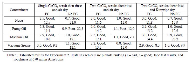
The results in the table indicate several things. First, the samples treated with First Contact
consistently have fewer pinholes than those without. The only samples with less than good tape
tests are the ones where First Contact wasn’t used. The two that did not pass the tape test both
had been exposed to pump oil. It is
possible that this oil does not come off well at the time the coating is
stripped and it does not clean off well using CaCO3. Finally, the roughness may be better in
samples using First Contact than those without, but this is not consistent in
all combinations. More will be said on
this later.
Oddly, one scrub and air dry and two scrubs and Kimwipe dry
produced better pinhole results, in conjunction with First Contact, than two
scrubs and air drying. At this point, we
have no good hypothesis to explain this result.
Given that there is a sample with and without First Contact
for each combination, it is reasonable to look at the twelve samples with First
Contact as a set and the twelve without as a second set. If this is done, then an average and standard
deviation over the sets can be done for the pinhole rankings and the surface
roughness. The results of these
calculations are: with First
Contact: Pinhole ranking = 2.6 ± 0.4,
Roughness = 11.9 ± 4.4 Angstroms; without First Contact: Pinhole ranking = 0.9
± 0.1, Roughness = 15.1 ± 7.0 Angstroms.
The improvement in pinhole ranking with First Contact is clear. There is also an apparent improvement in
roughness of about 3 Angstroms on average.
More significant is the size of the error bars which are based on the
standard deviation over all the measurements for each mirror (six measurements
on each mirror) in each group. In
addition to giving better roughness measurements, the samples using First
Contact gave more consistent roughness results than samples not prepared using
First Contact.
or this data set, the samples were also scanned using the
absolute reflectance attachment to our Shimadzu spectrophotometer. Again, all the curves were averaged depending
on whether First Contact had been used.
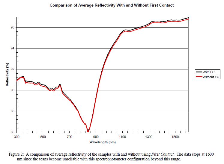
The curves are shown in Figure 2.
The standard deviation of the curves over the wavelength range plotted
is 0.13 ± 0.03% for the curve with First Contact and is 0.16 ± 0.03% for the
curve without First Contact.
Surprisingly, there is a small increase, on average, in the reflectivity
when using First Contact.
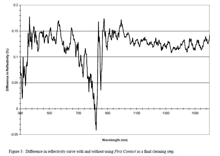
A plot of the difference between the two curves, Figure 3,
shows this gain in reflectivity even more distinctly. The dip at around 830 nm is likely caused by
a known calibration issue with the Shimadzu in this configuration at around 832
nm. If the difference is averaged over the plotted wavelength range, the
reflectivity increase when using First Contact is 0.12 ± 0.03%, including the
dip at around 800 nm. While the
difference between the two curves lies within the error bars for the curves,
taken to be the standard deviation of the curves over the wavelength range, the
fact that the difference is near the edge of the error bars indicates that some
level of increase is real.
ote that, in Figure 2, each curve is an average over twelve
separate samples. The samples were
cleaned and coated at the same time and scanned alternating between one with
First Contact and then one without since they were scanned by sample
number. In fact, all measurements on
these samples were done in sample number order at the same time without
reference to which procedure was performed on them. There is little chance that this increase in
reflectivity or improvement in the pinhole count or roughness is due to
instrument drift or some other systematic caused by unequal treatment of the
samples.
3.4 Experiment 3 Results
Experiment 3 was done in an attempt to see how well First
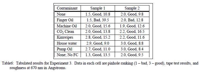
Contact could contend with substrate contamination after cleaning. The results, which are compiled in Table 6,
show that First Contact is able to remove many common sources of contamination
without further cleaning of the substrate.
The only coating failure was due to fingerprint contamination which
First Contact seems to be unable to lift off sufficiently to allow a good
coating, at least with only one application.
It is interesting to note that the pinhole ranking and
roughness measurements for most of the samples are consistent with the
measurements in Experiment 2 using two CaCO3 scrubs and air drying, which is
how these samples were all cleaned. Contaminating with Kimwipes, house water,
and pump oil, however, show improvements in pinhole ranking and in
roughness. There is no good explanation
for why these contaminants allow for better coating after removal by First
Contact.
The two samples where First Contact was not used were
somewhat better than what was achieved in Experiment 2 for any samples without
First Contact. These samples were
prepared and coated on the same day as the samples in Experiment 2.
These samples were also scanned with the Shimadzu
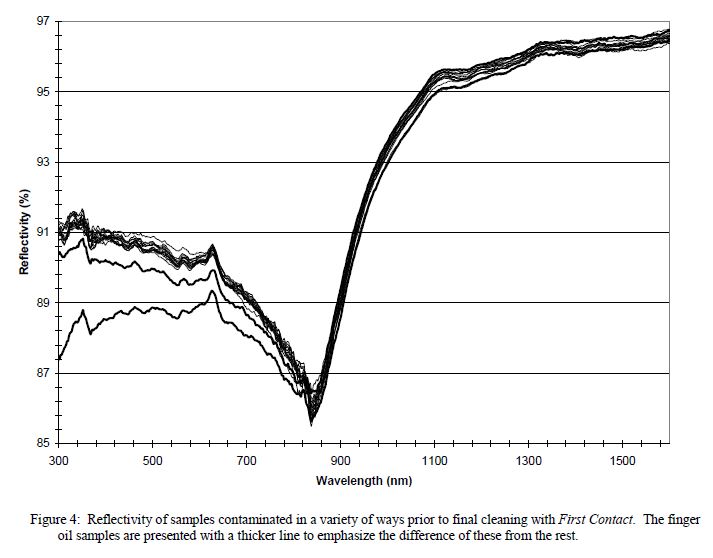
spectrophotometer prior to the tape tests.
All of the scans are shown in Figure 4.
The grouping of curves is similar to the grouping found in Experiment 2
with the exception of the two curves with finger oil contamination. Both of these show significant reflectivity
degradations in the blue, but only the first sample shows degradation in the
red. The level of contamination was
worse in sample 1 with finger oil.
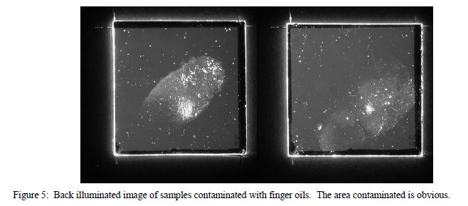
igure 5 shows the back illuminated photographs of the
samples contaminated with finger oil.
The area touched is clear although by eye, these samples did not show
strong signs of problems. One result to
take away from this experiment is that, in the words of one of the authors of
this paper, “Fingerprints are evil”, at least where coating is concerned. This indicates that if a surface is
contaminated with fingerprints, a thorough re-cleaning is necessary to achieve
good results.
Another significant result is that First Contact allowed a
good coating to take place even when the samples had been contaminated with
substances that would normally completely inhibit adhesion of the aluminum,
such as machine oil. Recall that these samples were not plasma cleaned prior to
coating which also helps to remove many oily contaminants.
In this experiment, no silicon-based oils, such as diffusion
pump oil, were used as contaminants. As
this is another common source of contamination, it would be very interesting to
see if First Contact were able to remove it as well.
4. CONCLUSIONS AND FUTURE WORK
These experiments have shown clearly that use of First
Contact as a final step in cleaning prior to coating works as well as standard
cleaning procedures. In fact, the
experiments indicated that a typical coating using First Contact as a final
cleaning step is much more likely to give better results in terms of pinhole
count than only using the standard cleaning procedure. Even when used poorly, as in Experiment 1,
use of First Contact still allows for an acceptable coating to happen, and when
used properly, can give excellent results.
In addition, many common contaminants that may creep back onto the
surface of a mirror after cleaning but prior to coating are removed with the
use of First Contact.
Excellent results can be obtained using the standard
procedure if great care is taken, as in Experiment 1. The succeeding experiments, however, show
that good to excellent results can be obtained more regularly if First Contact
is used. There was no sign that the surface roughness was increased with First
Contact, in fact the surface roughness seemed to improve. Finally, there were indications that a
slight, though probably not significant, increase in reflectivity is possible
when using First Contact.
The issues found with removing the First Contact from the
edges of the substrate will be investigated in the near future. We feel
confident that this is mainly due to the form factor of our substrates and
would be a non-issue on actual mirror substrates. This work will be done in consultation with
Photonic Cleaning Technologies to make sure that errors, like those in
Experiment 1, are not repeated.
It is hoped that the next step will be to use First Contact
in preparing our f/8 secondary prior to coating. This would help prove the concept on a larger
mirror, about 1.5 m diameter. The mirror
also has centering fiducials inscribed in the glass. This would show how First Contact works on a
substrate with surface defects.